nivek
As Above So Below
Convert a Lawn Mower into a Generator - Horizontal Mount (Part 1)
This article is based on a submission by David Hooper (with additions from the crew at TheEpicenter.com), which discusses building a generator from an old lawn mower and a GM alternator. We wanted to share them with you -- we looked at David's idea and loved it! We think we have improved upon his idea though, presenting our version in addition to David's input!
NOTE: This article is intended for educational purposes only. No guarantees are expressed or implied as to the accuracy of information presented here! Consult with an automotive wiring expert before attempting to carry out any wiring.
BUILDING YOUR OWN GENERATOR (ON THE CHEAP)...
The Project in David's own words
 "My standby battery charger for drag strip / RV use is now a "one wire" Marine alternator of 75 amp rating on a board (a 2 x 8) with a 3 HP horizontal shaft Tecumseh running the pulley. My first one, since sold, was a 3.5 HP Briggs & Stratton from a vertical shaft mower. I cut a slot in the front of the mower deck (but in retrospect, if I had to do it over, I would cut it in the back); then I added brackets made from old 1.5" angle iron for the pivot and an old (from the junkyard) slotted alternator bracket for the adjuster. By re-using the mower deck, I had a place to mount the entire works, on wheels with an easily attached (and detached) handle. If I had been even remotely bright at the time, I would have cut into the back of the deck, so that the alternator and mounts were under the handle, instead of sticking out the front which made the entire rig about a foot longer than it needed to be. Oh well.... (Live & Learn!).
"I actually used old bed frame rails for the angle iron to make the brackets. (My neighbor was tossing out an old bed, so the steel was free!).
"It isn't difficult to make this work. If you are after a syrstem to charge a battery between rounds so you can run the race car without an alternator, it works great! As a standby power source, the most expensive thing is the inverter. It has the advantage that you can run it to charge batteries, and subsequently run the inverter off the batteries for some light and silence! In an emergency, there is a battery in your car, one in your spouse's car, one in your neighbors car, etc. so there is no shortage of ability to store some power. Deep cycle (marine/RV) type batteries are greatly to be preferred, but if you don't have a boat or RV already, you are not likely to have them around, and the object of this project is to keep costs down while still avoiding "being powerless". If you are only after some light, use 12 V light fittings and bulbs, and save the cost of the inverter. Or use an inverter to run the heat recovery fan in your furnace/fireplace, and cycle it with the refrigerator / freezer to minimize the size of the inverter required and still use the 12 V lights."
We looked at David's idea and loved it!
We think we have improved upon his idea though...
Our Version of How to Build Your Own Generator (using a Horizontal Shaft Motor)
 We will discuss how to build your own generator that looks something like this (photo at left).
This generator was built using a 3 HP Briggs and Stratton horizontal shaft motor, a GM 65 amp automotive alternator (with built in voltage regulator), a used car battery, a pulley and V-belt, a 12 volt cigarette lighter outlet box with fuse, a DC to AC power converter, a low voltage control switch, a scrap of 3/4" plywood, a few scraps of 2 x 4 lumber, 4 wheels, and two battery cables. We also used a custom designed bracket manufactured for TheEpicenter.com to make it all come together in a snap.
In the photo above, we used an 8" pulley on the motor. Subsequent testing indicates that a 4" or 5" pulley is the correct size to use for this application.
Please note that a safety guard should be installed to cover the belt and pulleys! This guard is not installed so that the photographs show the most detail! If you plan to actually use a generator of this type. Please, Please make sure you install a safety guard!
What can this generator be used for?
The basic generator (gas powered motor, alternator and battery only) can be used as a 12 volt power source. This is extremely useful for charging battery banks in RVs, campers or in out buildings. The big advantage to this generator as a charging system is the high current output of the alternator, and thus, the reduced charge time over using solar cells, or AC battery chargers. The other big advantage to using this unit to charge batteries over merely charging them with a car, is that this generator
 uses much less gas to do the job (which is critical in an emergency). Some HAM radio folk use 12 volt equipment that can be powered from the battery until it is low in charge, and then crank up the generator to recharge the battery. The high output of this unit also makes it useful for car lots or fleets for jump starting cars.
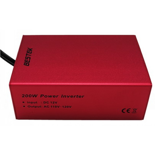
If a DC to AC power converter is added to the basic system, then a limited amount of 120 Volt AC power would also be available! DC to AC power converters electronically convert the 12 volt DC power to 60 hertz AC power at 120 volts. These devices just connect to the battery on the generator, and provide AC power outlets for standard household AC power.
What Used Motor Should You Use?
As David discussed, his first version of a home built generator used a vertical shaft lawn mower engine which are very easy to find (photo at left). These mowers can be had for a song and can be found just about anywhere. They have several of the key components that will be required in this project. They have a base that holds the motor, and a cable for adjusting the motor speed. They also have wheels which are very convenient if you ever plan to move it! The biggest task in making a home built generator is figuring out how to attach the alternator and motor so that power from the motor can be transferred to cause the alternator to spin, thereby producing electricity. The task is harder if a vertical shaft lawn mower engine is used.
The problem is that there are so many brands on the market, and each one it seams builds there own base. To make matters worse, there doesn't seem to be a really standard shape to the base. Some models have flat surfaces where items can be bolted to, and some bases don't.
You will notice that David's second generator used a horizontal shaft motor (photo at right) which greatly simplifies the whole project unless you have one of our special vertical shaft brackets for a lawn mower engine. The trick remains, actually mounting the alternator so a belt can be used to link the alternator to the motor. This task is simple when you use one of our horizontal mounting brackets.
Please Note: It IS possible to use a vertical shaft lawn mower engine if you use one of our special vertical brackets:
 +
+
 +
+
 =
=

Be sure to see the Vertical Shaft Project.
Build it using a Horizontal Shaft Motor
In this project, we will concentrate on how to build it using a horizontal shaft motor.
In the simplest form, the motor and alternator can each be bolted to a base. The exact mounting configuration of the alternator depends on the model of alternator , the motor used, and the belt drive configuration. The next task is to come up with a way to tension the belt. What some creative people do, (like David), is use miscellaneous brackets from cars to mount the alternator to a base. Then, adjuster brackets found on typical car engines are used to tension the belt on the alternator.
This method requires a high degree of "screwing around" to come up with (or build) the required brackets. Yes, a few trips to an automotive junk yard will result in finding miscellaneous useful items, but at a cost of several hours of time!
Time is Money!
The Epicenter.com crew has designed a simple way to carry out the bulk of this project:
 We have designed and manufactured a simple, one piece universal mounting bracket specifically for this task! This bracket bolts to the motor (using a universal bolt pattern), and allows the alternator to bolt directly to the bracket. The bracket also has an integral belt adjustment slot which allows the alternator position to be adjusted, which serves to tension the belt.
Shown at right: Bracket attached to another style of engine.
What will you need to build a home built generator?
 The first thing you will need is a used motor.
The key to this design is that it will require a horizontal shaft motor, which can be found on old drum style lawnmowers, roto-tillers, and lawn edgers. The most common motor size you will find on the used market will be a 3 or 3.5 horse power model. Larger motors are harder to find because most of them are snapped up for building go-carts or mini bikes. The most common brand you will find is a Briggs and Stratton. Newer Briggs and Stratton engines have the gas tank, carburetor and exhaust on the same side of the motor. If you look at the old style Briggs shown here, you will note that the gas tank is mounted on the opposite side of the motor than the carburetor. This means that which ever side the alternator is mounted on, the alternator must clear obstructions. Yes, our bracket takes this into account!
When buying a motor, note how the pulley is attached to the shaft. Most motor shafts have a square key way (or grove) cut in the shaft. This makes it super simple to replace the pulley with the type you will need for this project. Also note the shaft diameter. Most motors in the 3 horse power class have a 3/4"diameter shaft. Avoid purchasing a motor that only has a threaded hole in the end of the shaft! This configuration will prove to cause hours of wasted time figuring out how to attach the new pulley, as David found out when he built his first version!
You will notice that after looking at several motor models from several manufactures, there are a few features that just about all of them have. The first is that most have the keyed cut out in the output shaft. Secondly, they all have four bolt holes at the base for mounting the motor to a flat surface. Thirdly, they all have four tapped holes on the output shaft cover plate. These output cover plate mounting holes are a key feature of horizontal shaft motors. Be sure the motor you purchase has them if you plan to use a bracket like the one we designed!
How do you know if your motor has the required holes?
 Look at where the output shaft is on the motor. Then, notice that there are two holes above, and two holes below the shaft. They will be located on an imaginary circle, 3-5/8" in diameter, and centered at the shaft center. It sounds more complicated than it really is. Take a look at the diagram.
We have looked at motors ranging from 3 to 10 horse power, and have discovered that these output cover bolt holes are in one of two patterns.
The following motors use a 3-5/8th inch bolt hole circle:
Check the location of the gas tank
 The photo at left is a Top View of a Briggs and Stratton 3 Horse Power Motor found on lawn edgers. It shows the location of the gas tank.
Most newer motors have the tank, carburetor and muffler on the same side of the motor. In the case of the 3 horse power Briggs and Stratton we used, the tank is on the opposite side. The next thing to determine is if the side of the tank extends beyond the flat surface of the output shaft cover plate. As seen from this top view, the 3 horse power Briggs does (which adds a bit of complication to mounting the generator). Our bracket has a cutout which is designed to clear gas tanks of this type.
The next thing you need is an Alternator (with built in voltage regulator)
The power source: A GM alternator
We also used a 65 amp GM alternator with a built in voltage regulator. It is critical that you only use an alternator that has a built in voltage regulator! If you make a mistake in the selection of the alternator you run a very high risk of damaging the battery, or worse yet, causing personal injury!
Again, pay special attention to the selection of the alternator! You must select a GM alternator with a built-in voltage regulator. If you are in doubt, consult an expert or parts professional!
To fully understand the reason for the special notice above, let's review a few things about how an alternator works:
We are going to skip significant details relating to magnetics and take a leap of faith; here we describe the effect seen when an alternator is turned--either one that has a built in voltage regulator, or one that does NOT have a built in voltage regulator. (This discussion assumes that the terminals are connected as they would normally be, and no additional details will be provided for this discussion.)
In the case of an alternator that does NOT have a built in voltage regulator: (very , very bad - don't use!):
 The pins on a Delco-Remy 1100934 37A, 3D10 12VNEG alternator with built-in voltage regulator.
Consult a parts professional for additional wiring information!
Another note: When the time comes to crank up your generator, you will need to turn off the switch that goes to the "R"terminal. If the switch is on, the generator will try to output voltage while you are pulling the starting cord on the motor. You will find that it will be nearly impossible to pull the cord! If the switch is off, then there is little to no resistance from the alternator.
What else is needed?
The Pulley (attach to the motor output shaft)
 In our prototype shown above, we used an 8" pulley (with a 3/4" shaft, and key way). What we found was that the gearing ratio was less than ideal. We have run additional tests, and determined that a 4" or 5" diameter pulley is correct for this application. Either a 6" or an 8" will work if you can't find a 4" or 5", but you will notice that the motor speed decreases as a load is applied. To compensate (if using a 6" or 8" pulley), the motor speed would need to be increased prior to a load being turned on.
With the 8" on the motor, and the motor set to idle, we were able to kill the motor when a 150 Watt load was applied. If the motor speed was set above idle, there wasn't much of a problem, but the alternator was spinning much faster than is required. A 6" pulley under the same conditions resulted in a slight motor speed decrease when the load was applied. The alternator speed was about right. But when a 4" or 5" pulley was used, there was no motor speed change for the same load. In fact, it handled the load while running at idle speed, and turned the alternator at a speed more like found in a car.
Pulley and Belt Data when using TheEpicenter.com's Alternator Bracket
Pulley
Diameter Usability Minimum belt
length Maximum belt
length
4" Excellent 35" 37"
5" Really good 36" 38"
6" Usable 38" 40"
8" Undesirable but works 41" 43"
The following email conversation between TheEpicenter.com crew and David Hooper illustrates the problem:
TheEpicenter.com asked David Hooper the following:
"David, I noticed that when I built up a generator using an 8"pulley on the motor, that the motor was not in its normal power range. The Alternator was also spinning like crazy, and I think it would all work better if the pulley ratio was closer to something you would find in a car, like a 5"or 6"pulley on the motor. That would spin the alternator more at a speed like found in the car, and would also increase the torque seen at the alternator, so load changes would have less affect on the motor."
David responded:
"I'll go measure, but it seems to me that I tried to use one about an inch or two bigger (diameter) than the size of the alternator pulley so that, with the engine at its 'cruise speed' (about 2500 RPM) the alternator would be at reasonable speed as well - it doesn't put out its max power unless its really humming, but you can't run it 'flat out' forever either, and you've only got about 3 or 3.5 hp to power it! Everything is a compromise!"
"I'd try the 5"but it seems to me that mine was more like a 4"- memory fails at this point...Yes the alternator will drag down the engine speed, but if you are over geared, it will REALLY do it!"
In a follow-up email from David:
"The 5 inch pulley should do it. You are absolutely correct in assuming that one of about the same size as is used in the car (about a 6") would be correct to give the right alternator speed. But remember that most cars spend much of their lives well BELOW 2500 rpm, so the pulley is sized to give a compromise belt speed for water pump, fan, alternator, etc. In fact many cars have a 'stepped' pulley with a different size for running the Power Steering pump, and yet another for the A/C.
"Here we have a dedicated unit, with only a 3 - 3.5 hp engine, so somewhere in the 5 - 6 inch range should be about it. I never really did any experimenting with different sizes and measuring max output of the alternator. Does going up from the 5" to the 6" increase output, or drag the motor rpm down for a net loss? Interesting question!
"I just used some 'stuff on hand' and it worked, so I the proceeded to the old maxim 'If it works, don't fix it!' Perhaps a bit of tinkering might be order after all!"
The Cables
 The small 2 wire plug (shown at the right) is also available from TheEpicenter.com. This molded connector (with wires) is a replacement part for hooking into the two terminals (R, and F) on the alternator. It saved a bunch of time making two of the alternator connections and is well worth the cost.
Next, we used standard 6 gauge, 15" battery cables to connect the alternator to the battery. Yes, they are a bit over-kill, but the amount of time you would spend making your own cables of lesser wire size (crimping the terminals etc.) is more than the cost of just buying a pair!
We had a note from David on the subject, and will share it with you:
"I suspect that the use of 'full on' battery cables is overkill; there are battery terminals that take wing nut & screw (post) connectors available at many auto/RV stores, and you don't need to have all that much thickness of wire here. Check out the gauge of the wires from the alternator to the battery of a car--about 8 ga should do, 6 ga if you really want a safety factor. The "2", "1", "0"or "00" ga. wires in battery cables are just overkill in this application; they ARE needed in a car to transmit the large current needed by the starter, but at no other time. Leave 'em in as optional, but costs can be possibly reduced by using cheaper wires (unless the auto parts store has battery cables at really cheap prices!) My concern is the size of connector needed at the alternator end. Getting that connector to fit the 'hot' terminal of the alternator without any danger of it touching the case or any other 'ground' is easier with smaller terminals, hence smaller wires!"
The actual length you will require may be longer depending on how you mount everything. 15" is about the minimum length.
OK, so how does all this junk hook together?
 Shown at left: A top view of the components (belt guard removed).
The first thing to do is to lay out all the components on your shop floor. This will give you an idea of how much space you will need to mount all the items on a base. We found that the smallest size for the platform was the size of some scrap plywood from out back. The minimum size is 28" long, and 15" wide if the battery is mounted close to the alternator. This allows the use of less expensive 15" battery cables. Also note the location of the power converter. You will need access to the front of the unit to plug in AC devices; this access needs to be away from the belt and pulley.
This configuration also provides easy access to the motor starting cord.
Please note! Add about 4 inches to the minimum width of the platform so that a guard can be built to cover the pulley and belt! This prototype was built without a guard so that pictures could be taken, and was not intended to really be used! This is a very dangerous configuration when a belt cover is not installed! Please, Please install a belt and pulley guard for the safety of others! A safety guard can be built using scraps of 2 x 4s, and another scrap of plywood.
The next step is to bolt the alternator adapter bracket to the motor, and bolt the alternator to the bracket. Then check the placement on your mounting platform. You will also need to verify the mounting hole dimensions for your motor. The Briggs and Stratton 3 HP we used has a bolt pattern as shown below:
 Shown at left: The Briggs and Stratton - Motor mounting hole pattern for a 3 HP
Be sure to check your motor for the correct mounting hole locations. Then drill the holes in the plywood mounting base slightly over-size to aid in positioning the motor. In the case of the motor we used, the bolt holes are 1/4", so we drilled the holes 3/8" to give a bit of slop so the bolts go into the base a bit easier.
Now position the battery on the base.
 Provide at least 3" of space between the rear of the alternator and the battery. This will provide ample space for access to the alternator terminals. Next, use some scrap chunks of 2 x 4s positioned with the 2"side down, to build a 4"tall box around the battery. We cut them to length, and then secured them to the base from underneath using 2" wood screws.
It's much easier if the holes are drilled before trying to install the screws. What we did was to cut the first 2x4, then positioned it on the far side of the battery. We marked the outer location with a pencil. Then we moved the battery, and marked the inside of the 2x4. We did the same thing for the other 3 scraps. Once the outlines of the 2x4s were marked, we "pre drilled"the holes in the base. Next, we positioned the 2x4s (one at a time) back on the base, and drilled into the bottom of the 2x4s from the opposite side of the base, using the holes in the base as a drill guide. Then we installed the screws through the base and into the 2x4 scraps. Once complete, the battery fits right in the box!
Next, install any type of wheels you might have on hand. We used a few wheels with casters, but if you have an old lawnmower around, those wheels would work even better!
And finally, bolt the motor to the base, do the required wiring, and install the battery.
How to Wire it Up
This information is intended for educational purposes only. No guarantees are expressed or implied as to the accuracy of information presented here! Consult with an automotive wiring expert before attempting to carry out any wiring.
 The basic wiring.
This is the basic configuration using a Delco-Remy 1100934 37A, 3D10 12VNEG alternator only. Consult with a parts professional for wiring information.
In this mode, it can only be used for 12 volt DC applications. A 12 volt cigarette lighter outlet box can be added to provide an easy way to connect 12 volt devices to the unit. I f a cigarette lighter outlet is added, be sure to install a fuse in line with the outlet box. Most boxes that can be purchased at an auto parts store come with one. But remember that the amount of power that can be delivered when cigarette lighter sockets are used, can only be as much as follows:
Say the lighter outlet box you select has a 20 amp fuse. Then the maximum power that can be delivered through the connector is 12 Volts x 20 amps = 240 Watts. That means that no appliance can draw more than 240 watts or the fuse will blow. So, if you plan to use a 140 watt, 200 peak DC to AC power converter at full load, it will work fine. But if you elect to use a larger model at full capacity using the cigarette lighter plug, you will blow the fuse! Larger models than the 140 watt unit will require that you wire it directly to the battery.
Do not attempt to replace the fuse with a higher value!
What does it look like when finished?
Front View of Completed Generator
 Rear View of Completed Generator
This article is based on a submission by David Hooper (with additions from the crew at TheEpicenter.com), which discusses building a generator from an old lawn mower and a GM alternator. We wanted to share them with you -- we looked at David's idea and loved it! We think we have improved upon his idea though, presenting our version in addition to David's input!
NOTE: This article is intended for educational purposes only. No guarantees are expressed or implied as to the accuracy of information presented here! Consult with an automotive wiring expert before attempting to carry out any wiring.
BUILDING YOUR OWN GENERATOR (ON THE CHEAP)...
The Project in David's own words
"I actually used old bed frame rails for the angle iron to make the brackets. (My neighbor was tossing out an old bed, so the steel was free!).
"It isn't difficult to make this work. If you are after a syrstem to charge a battery between rounds so you can run the race car without an alternator, it works great! As a standby power source, the most expensive thing is the inverter. It has the advantage that you can run it to charge batteries, and subsequently run the inverter off the batteries for some light and silence! In an emergency, there is a battery in your car, one in your spouse's car, one in your neighbors car, etc. so there is no shortage of ability to store some power. Deep cycle (marine/RV) type batteries are greatly to be preferred, but if you don't have a boat or RV already, you are not likely to have them around, and the object of this project is to keep costs down while still avoiding "being powerless". If you are only after some light, use 12 V light fittings and bulbs, and save the cost of the inverter. Or use an inverter to run the heat recovery fan in your furnace/fireplace, and cycle it with the refrigerator / freezer to minimize the size of the inverter required and still use the 12 V lights."
We looked at David's idea and loved it!
We think we have improved upon his idea though...
Our Version of How to Build Your Own Generator (using a Horizontal Shaft Motor)
This generator was built using a 3 HP Briggs and Stratton horizontal shaft motor, a GM 65 amp automotive alternator (with built in voltage regulator), a used car battery, a pulley and V-belt, a 12 volt cigarette lighter outlet box with fuse, a DC to AC power converter, a low voltage control switch, a scrap of 3/4" plywood, a few scraps of 2 x 4 lumber, 4 wheels, and two battery cables. We also used a custom designed bracket manufactured for TheEpicenter.com to make it all come together in a snap.
In the photo above, we used an 8" pulley on the motor. Subsequent testing indicates that a 4" or 5" pulley is the correct size to use for this application.
Please note that a safety guard should be installed to cover the belt and pulleys! This guard is not installed so that the photographs show the most detail! If you plan to actually use a generator of this type. Please, Please make sure you install a safety guard!
What can this generator be used for?
The basic generator (gas powered motor, alternator and battery only) can be used as a 12 volt power source. This is extremely useful for charging battery banks in RVs, campers or in out buildings. The big advantage to this generator as a charging system is the high current output of the alternator, and thus, the reduced charge time over using solar cells, or AC battery chargers. The other big advantage to using this unit to charge batteries over merely charging them with a car, is that this generator
If a DC to AC power converter is added to the basic system, then a limited amount of 120 Volt AC power would also be available! DC to AC power converters electronically convert the 12 volt DC power to 60 hertz AC power at 120 volts. These devices just connect to the battery on the generator, and provide AC power outlets for standard household AC power.
What Used Motor Should You Use?
As David discussed, his first version of a home built generator used a vertical shaft lawn mower engine which are very easy to find (photo at left). These mowers can be had for a song and can be found just about anywhere. They have several of the key components that will be required in this project. They have a base that holds the motor, and a cable for adjusting the motor speed. They also have wheels which are very convenient if you ever plan to move it! The biggest task in making a home built generator is figuring out how to attach the alternator and motor so that power from the motor can be transferred to cause the alternator to spin, thereby producing electricity. The task is harder if a vertical shaft lawn mower engine is used.
The problem is that there are so many brands on the market, and each one it seams builds there own base. To make matters worse, there doesn't seem to be a really standard shape to the base. Some models have flat surfaces where items can be bolted to, and some bases don't.
You will notice that David's second generator used a horizontal shaft motor (photo at right) which greatly simplifies the whole project unless you have one of our special vertical shaft brackets for a lawn mower engine. The trick remains, actually mounting the alternator so a belt can be used to link the alternator to the motor. This task is simple when you use one of our horizontal mounting brackets.
Please Note: It IS possible to use a vertical shaft lawn mower engine if you use one of our special vertical brackets:
Be sure to see the Vertical Shaft Project.
Build it using a Horizontal Shaft Motor
In this project, we will concentrate on how to build it using a horizontal shaft motor.
In the simplest form, the motor and alternator can each be bolted to a base. The exact mounting configuration of the alternator depends on the model of alternator , the motor used, and the belt drive configuration. The next task is to come up with a way to tension the belt. What some creative people do, (like David), is use miscellaneous brackets from cars to mount the alternator to a base. Then, adjuster brackets found on typical car engines are used to tension the belt on the alternator.
This method requires a high degree of "screwing around" to come up with (or build) the required brackets. Yes, a few trips to an automotive junk yard will result in finding miscellaneous useful items, but at a cost of several hours of time!
Time is Money!
The Epicenter.com crew has designed a simple way to carry out the bulk of this project:
Shown at right: Bracket attached to another style of engine.
What will you need to build a home built generator?
The key to this design is that it will require a horizontal shaft motor, which can be found on old drum style lawnmowers, roto-tillers, and lawn edgers. The most common motor size you will find on the used market will be a 3 or 3.5 horse power model. Larger motors are harder to find because most of them are snapped up for building go-carts or mini bikes. The most common brand you will find is a Briggs and Stratton. Newer Briggs and Stratton engines have the gas tank, carburetor and exhaust on the same side of the motor. If you look at the old style Briggs shown here, you will note that the gas tank is mounted on the opposite side of the motor than the carburetor. This means that which ever side the alternator is mounted on, the alternator must clear obstructions. Yes, our bracket takes this into account!
When buying a motor, note how the pulley is attached to the shaft. Most motor shafts have a square key way (or grove) cut in the shaft. This makes it super simple to replace the pulley with the type you will need for this project. Also note the shaft diameter. Most motors in the 3 horse power class have a 3/4"diameter shaft. Avoid purchasing a motor that only has a threaded hole in the end of the shaft! This configuration will prove to cause hours of wasted time figuring out how to attach the new pulley, as David found out when he built his first version!
You will notice that after looking at several motor models from several manufactures, there are a few features that just about all of them have. The first is that most have the keyed cut out in the output shaft. Secondly, they all have four bolt holes at the base for mounting the motor to a flat surface. Thirdly, they all have four tapped holes on the output shaft cover plate. These output cover plate mounting holes are a key feature of horizontal shaft motors. Be sure the motor you purchase has them if you plan to use a bracket like the one we designed!
How do you know if your motor has the required holes?
We have looked at motors ranging from 3 to 10 horse power, and have discovered that these output cover bolt holes are in one of two patterns.
The following motors use a 3-5/8th inch bolt hole circle:
- Briggs and Stratton 3, 3.5, 5 horse power
- Robin International 5 horse power
- Tecumseh 5,6,7,8,10 horse power
- Honda 5.5 horse power
Check the location of the gas tank
Most newer motors have the tank, carburetor and muffler on the same side of the motor. In the case of the 3 horse power Briggs and Stratton we used, the tank is on the opposite side. The next thing to determine is if the side of the tank extends beyond the flat surface of the output shaft cover plate. As seen from this top view, the 3 horse power Briggs does (which adds a bit of complication to mounting the generator). Our bracket has a cutout which is designed to clear gas tanks of this type.
The next thing you need is an Alternator (with built in voltage regulator)
We also used a 65 amp GM alternator with a built in voltage regulator. It is critical that you only use an alternator that has a built in voltage regulator! If you make a mistake in the selection of the alternator you run a very high risk of damaging the battery, or worse yet, causing personal injury!
Again, pay special attention to the selection of the alternator! You must select a GM alternator with a built-in voltage regulator. If you are in doubt, consult an expert or parts professional!
To fully understand the reason for the special notice above, let's review a few things about how an alternator works:
We are going to skip significant details relating to magnetics and take a leap of faith; here we describe the effect seen when an alternator is turned--either one that has a built in voltage regulator, or one that does NOT have a built in voltage regulator. (This discussion assumes that the terminals are connected as they would normally be, and no additional details will be provided for this discussion.)
In the case of an alternator that does NOT have a built in voltage regulator: (very , very bad - don't use!):
- As the unit is rotated, the output voltage increases. The faster it rotates, the higher the output voltage goes! So, if it is rotated at several thousand RPM, the output voltage would reach 70+ volts! This condition is enough to boil the electrolyte in a battery and could cause explosive results! Do not use this type of alternator!
- Now, if an alternator that has a built in voltage regulator is used (and properly connected), the output voltage will increase until it reaches about 14 volts. That's it. No matter how fast it is rotated, the output will never go above that value. As it turns out, this is the ideal charging voltage for a lead acid battery (a standard car battery). Imagine that!
Consult a parts professional for additional wiring information!
Another note: When the time comes to crank up your generator, you will need to turn off the switch that goes to the "R"terminal. If the switch is on, the generator will try to output voltage while you are pulling the starting cord on the motor. You will find that it will be nearly impossible to pull the cord! If the switch is off, then there is little to no resistance from the alternator.
What else is needed?
The Pulley (attach to the motor output shaft)
With the 8" on the motor, and the motor set to idle, we were able to kill the motor when a 150 Watt load was applied. If the motor speed was set above idle, there wasn't much of a problem, but the alternator was spinning much faster than is required. A 6" pulley under the same conditions resulted in a slight motor speed decrease when the load was applied. The alternator speed was about right. But when a 4" or 5" pulley was used, there was no motor speed change for the same load. In fact, it handled the load while running at idle speed, and turned the alternator at a speed more like found in a car.
Pulley and Belt Data when using TheEpicenter.com's Alternator Bracket
Pulley
Diameter Usability Minimum belt
length Maximum belt
length
4" Excellent 35" 37"
5" Really good 36" 38"
6" Usable 38" 40"
8" Undesirable but works 41" 43"
The following email conversation between TheEpicenter.com crew and David Hooper illustrates the problem:
TheEpicenter.com asked David Hooper the following:
"David, I noticed that when I built up a generator using an 8"pulley on the motor, that the motor was not in its normal power range. The Alternator was also spinning like crazy, and I think it would all work better if the pulley ratio was closer to something you would find in a car, like a 5"or 6"pulley on the motor. That would spin the alternator more at a speed like found in the car, and would also increase the torque seen at the alternator, so load changes would have less affect on the motor."
David responded:
"I'll go measure, but it seems to me that I tried to use one about an inch or two bigger (diameter) than the size of the alternator pulley so that, with the engine at its 'cruise speed' (about 2500 RPM) the alternator would be at reasonable speed as well - it doesn't put out its max power unless its really humming, but you can't run it 'flat out' forever either, and you've only got about 3 or 3.5 hp to power it! Everything is a compromise!"
"I'd try the 5"but it seems to me that mine was more like a 4"- memory fails at this point...Yes the alternator will drag down the engine speed, but if you are over geared, it will REALLY do it!"
In a follow-up email from David:
"The 5 inch pulley should do it. You are absolutely correct in assuming that one of about the same size as is used in the car (about a 6") would be correct to give the right alternator speed. But remember that most cars spend much of their lives well BELOW 2500 rpm, so the pulley is sized to give a compromise belt speed for water pump, fan, alternator, etc. In fact many cars have a 'stepped' pulley with a different size for running the Power Steering pump, and yet another for the A/C.
"Here we have a dedicated unit, with only a 3 - 3.5 hp engine, so somewhere in the 5 - 6 inch range should be about it. I never really did any experimenting with different sizes and measuring max output of the alternator. Does going up from the 5" to the 6" increase output, or drag the motor rpm down for a net loss? Interesting question!
"I just used some 'stuff on hand' and it worked, so I the proceeded to the old maxim 'If it works, don't fix it!' Perhaps a bit of tinkering might be order after all!"
The Cables
Next, we used standard 6 gauge, 15" battery cables to connect the alternator to the battery. Yes, they are a bit over-kill, but the amount of time you would spend making your own cables of lesser wire size (crimping the terminals etc.) is more than the cost of just buying a pair!
We had a note from David on the subject, and will share it with you:
"I suspect that the use of 'full on' battery cables is overkill; there are battery terminals that take wing nut & screw (post) connectors available at many auto/RV stores, and you don't need to have all that much thickness of wire here. Check out the gauge of the wires from the alternator to the battery of a car--about 8 ga should do, 6 ga if you really want a safety factor. The "2", "1", "0"or "00" ga. wires in battery cables are just overkill in this application; they ARE needed in a car to transmit the large current needed by the starter, but at no other time. Leave 'em in as optional, but costs can be possibly reduced by using cheaper wires (unless the auto parts store has battery cables at really cheap prices!) My concern is the size of connector needed at the alternator end. Getting that connector to fit the 'hot' terminal of the alternator without any danger of it touching the case or any other 'ground' is easier with smaller terminals, hence smaller wires!"
The actual length you will require may be longer depending on how you mount everything. 15" is about the minimum length.
OK, so how does all this junk hook together?
The first thing to do is to lay out all the components on your shop floor. This will give you an idea of how much space you will need to mount all the items on a base. We found that the smallest size for the platform was the size of some scrap plywood from out back. The minimum size is 28" long, and 15" wide if the battery is mounted close to the alternator. This allows the use of less expensive 15" battery cables. Also note the location of the power converter. You will need access to the front of the unit to plug in AC devices; this access needs to be away from the belt and pulley.
This configuration also provides easy access to the motor starting cord.
Please note! Add about 4 inches to the minimum width of the platform so that a guard can be built to cover the pulley and belt! This prototype was built without a guard so that pictures could be taken, and was not intended to really be used! This is a very dangerous configuration when a belt cover is not installed! Please, Please install a belt and pulley guard for the safety of others! A safety guard can be built using scraps of 2 x 4s, and another scrap of plywood.
The next step is to bolt the alternator adapter bracket to the motor, and bolt the alternator to the bracket. Then check the placement on your mounting platform. You will also need to verify the mounting hole dimensions for your motor. The Briggs and Stratton 3 HP we used has a bolt pattern as shown below:
Be sure to check your motor for the correct mounting hole locations. Then drill the holes in the plywood mounting base slightly over-size to aid in positioning the motor. In the case of the motor we used, the bolt holes are 1/4", so we drilled the holes 3/8" to give a bit of slop so the bolts go into the base a bit easier.
Now position the battery on the base.
It's much easier if the holes are drilled before trying to install the screws. What we did was to cut the first 2x4, then positioned it on the far side of the battery. We marked the outer location with a pencil. Then we moved the battery, and marked the inside of the 2x4. We did the same thing for the other 3 scraps. Once the outlines of the 2x4s were marked, we "pre drilled"the holes in the base. Next, we positioned the 2x4s (one at a time) back on the base, and drilled into the bottom of the 2x4s from the opposite side of the base, using the holes in the base as a drill guide. Then we installed the screws through the base and into the 2x4 scraps. Once complete, the battery fits right in the box!
Next, install any type of wheels you might have on hand. We used a few wheels with casters, but if you have an old lawnmower around, those wheels would work even better!
And finally, bolt the motor to the base, do the required wiring, and install the battery.
How to Wire it Up
This information is intended for educational purposes only. No guarantees are expressed or implied as to the accuracy of information presented here! Consult with an automotive wiring expert before attempting to carry out any wiring.
This is the basic configuration using a Delco-Remy 1100934 37A, 3D10 12VNEG alternator only. Consult with a parts professional for wiring information.
In this mode, it can only be used for 12 volt DC applications. A 12 volt cigarette lighter outlet box can be added to provide an easy way to connect 12 volt devices to the unit. I f a cigarette lighter outlet is added, be sure to install a fuse in line with the outlet box. Most boxes that can be purchased at an auto parts store come with one. But remember that the amount of power that can be delivered when cigarette lighter sockets are used, can only be as much as follows:
Say the lighter outlet box you select has a 20 amp fuse. Then the maximum power that can be delivered through the connector is 12 Volts x 20 amps = 240 Watts. That means that no appliance can draw more than 240 watts or the fuse will blow. So, if you plan to use a 140 watt, 200 peak DC to AC power converter at full load, it will work fine. But if you elect to use a larger model at full capacity using the cigarette lighter plug, you will blow the fuse! Larger models than the 140 watt unit will require that you wire it directly to the battery.
Do not attempt to replace the fuse with a higher value!
What does it look like when finished?
Front View of Completed Generator